Universal Solenoid Driver
Available from Q1/2026: Next Generation Solenoid Driver by Sonplas
The upcoming version will offer, among other features:
- 1 channel for full performance
- 150 V nominal operation voltage up to max. 200 V
- Continuous bi-directional output voltage
- 10 Arms and 50 Apeak output current at up to 200V
- Algorithm for determining the injector closing time using the delta voltage method
- Voltage measurement at output terminals or through sense terminals at device
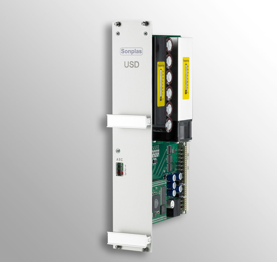
The Universal Solenoid Driver, USD for short, is a 2-channel programmable power amplifier with FPGA controller-supported digital current control especially for controlling automotive inductors (not piezo).
Intended purpose:
- Time-synchronous control of injectors, valves of high-pressure pumps, hydraulic valves, pressure and volume control valves.
Examples: Flow measurement of injectors (also shot-to-shot) or spray test. - Angle synchronised control is also possible with additional hardware that triggers the Universal Solenoid Driver.
Example: Petrol / diesel high pressure pump control
Highlights
- Up to 63 cards on one RS485 communication network and up to 255 communication networks.
- 2 channels, each with up to 31 current phase sections per channel
- Paging function per channel, for trouble-free switching between two control profiles.
- Three different voltages from external sources to drive the load:
Vbatt / Vboost1 / Vboost2 - Fully digital current control
- Various triggering possibilities as a step-on condition and for switching the pulse generation on and off:
Trigger internal, external pos. / neg. edge with and without delay, peak current, time - Demagnetisation voltage: Freerun, -Vbatt / -Vboost1 / -Vboost2
Technical data
- Control supply: 20.0V – 28.0V DC, 350mA @ 24V DC
- Load voltages external: V batt / V boost1 / V boost2 (Abs. max. 0 – 100Vdc)
- Buffer capacity load voltages: per load voltage 2×820µF / 100V
- Continuous current (max.): 20A RMS @ 20°C
- Current measurement:
- Resolution: 16 bit, sampling: 500 kS/s
- Range: type up to 27A (max. 30A)
- Basic sensor accuracy: +/- 0.6% @25°C
- Max. current increase: +30A/µs
- Voltage measurement: ± 110 V, 16 bit / 500 kS/s, ±0.2% voltage divider tolerance
- Monitoring:
- Resolution: 12 bit
- Vbatt/Vboost: 0–100 V, ±500 mV
- Heatsink: ±1 °C
- Environs: +10°C..+40° rel. humidity <95% non-condensing (IEC 60721-3-1)
- Degree of soiling: 2 (PD2, IEC 61010)
- Type: IEC 60 297-3-100
- Dimensions: 19″, 6 RU / 10 HP (261.8 × 50.5 mm), PCB 233 × 160 mm
- Weight: 870g
All data refer to a current hardware version at the time of creation (HW V1.5, FW V5.10 rev03).